All Jewelry CAD Designers MUST READ this prior to beginning work on Design Projects to ensure that designs are optimized for production.
Please keep an eye out for emails and update to this page to stay up-to-date on changes.
Overview -
Gildform's production process is as follows 3D printing, Lost-Wax Casting, Spruing/Investing, Polishing, Assembling and Plating (depending on given order specifications).
- Each 3D Model must be optimized for production, meaning that it is made within the production standards and capabilities.
- Each 3D model and it's details must be sized with the consideration of 3D printing, Casting, Polishing and Assembly. Certain dimensions and tolerances are not possible with consideration of the processes, so designs must be within these limitations.
Out-of-Scope Capabilities
Below is a list of capabilities that are currently out-of-scope for Gildform's production. We do expect some of these capabilities to become available in the future, however, at this time it is not currently available. Please verify and confirm this with Customers prior to beginning the design project.
- Laser Engraving / cutting
- Hinge-Making, clasps or any design with spring mechanism.
- Interlocking parts, mechanical parts or other similar characteristics
- Stone Setting
- Some specialty assembly such as beading.
- Anything larger than 3in x 4in
If you have questions about capabilities and would like to verify things with production.
Please submit your questions to the Gildform Community slack channel.
Gildform Team and fellow Jewelry CAD Designers may provide you with assistance on your inquiry.
Jewelry CAD Designers may request an invite by emailing hello@gildform.com
Approved Jewelry CAD Designers will be added to the slack community automatically.
Gildform's Terms Of Service apply.
DESIGN GUIDE FOR JEWELRY CAD DESIGNERS
Basic Design Parameters, Supports, and Orientation or 3D Printed Jewelry
Introduction
This paper presumes a working knowledge of a CAD modeling program with files that can be converted to STL or OBJ format. We used Rhino5, but the same principles apply to any CAD software that you are comfortable with. The models shown as examples make no claim to aesthetic value, but were created to demonstrate the principles described.
Another technical process, casting, should also influence the way the model is designed. Just because you are able to 3D print a model does not mean that it will cast or be successfully finished (polished and/or assembled).
PRINTING PROCESS
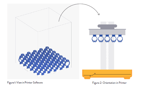
Our 3D printer uses a laser to harden a layer of resin between two surfaces submerged in the resin tank in a process called curing. The laser traces a path in a layer of resin determined by the cross section of your piece at many different heights, and begins at the “bottom” of your piece as it appears in the 3D Printer’s software, which aids this process by slicing your piece in thicknesses determined by the layer height you choose.
For jewelry models with fine detail, a layer height of 25 microns is recommended.
During the laser hardening process, the resin adheres strongly to the build platform and subsequent layers of resin, and adheres weakly to the optically clear silicone surface of the resin tank. The thickness of each build layer is determined by the distance between the two surfaces. For example, when you set a 50-micron layer thickness in the 3D Printer Software, the machine will use that thickness to set the distance between surfaces for each subsequent layer (Fig 3 ..1)
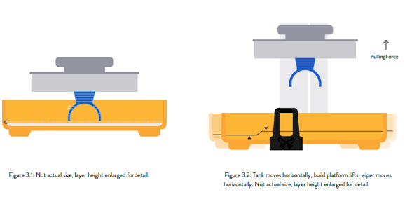
After each layer hardens, the build platform and attached layers must peel away from the silicone surface of the resin tank. The resin tank moves sideways relative to the build platform to accomplish this, and must overcome the adhesion and suction forces holding the resin layer to the silicone surface. Although necessarily weaker than the forces holding the part to the build platform, these sideway forces can cause distortion or failure in the printed part if not compensated for.
The flow of resin in the tank generated by the sideways peel motion is another force acting against the part The build platform rises above the surface of the resin tank to allow the wiper to clear the build area from any debris or particulate that might interfere with hardening the next layer, and circulates the resin in the tank (Fig 3.2)
The various resins used for printing are initially hardened into shape with a laser beam. This initial forming process does not completely harden the resin 3D prints straight off the machine are often referred to as being in the “green state ”.
After the print is finished, it must then be fully cured by a combination of heat and light. Standard materials, such as Grey, White, and Black, can be used for presentation models in the green state without additional curing Functional resins, and particularly Castable Resin, require additional curing, as they are quite soft in the green state.
A fully cured part will lead to better casting success. Thin parts cure more easily than thick parts, and a benefit of thin and light parts is that they have less mass to be controlled during the peel process.
We use a Castable Wax Resin which require no additional curing.
Figure 3.1: Not actual size, layer height enlarged for detail. Figure 3.2: Tank moves horizontally, build platform lifts, wiper moves horizontally.
Basics of Digital Design for Printing and Casting - OVERVIEW
Aside from creating beautiful designs, jewelry designers need to work within the parameters of cost and process by paying close attention to wall thicknesses and weight. Jewelry is typically designed to keep weight down due to costs of materials (precious metals) and wearability yet give the illusion of reassuring volume.
Keeping the weight down and wall thicknesses relatively thin helps achieve successful prints in a shorter time and requires less resin for the build.
The casting process has its own parameters for success, which will be addressed in this section Just because we can print your design does not mean that we can successfully cast it!
This guide presents a broad survey of some of the basics of digital design for jewelry printing and casting, and as such will only look at some basic principles and explanations. Please note that the following information is given as one of many approaches to the technical aspects of digital modeling, and we welcome feedback if you agree, disagree, or have a different way of modeling jewelry.
WEIGHT AND WALL THICKNESS
As described earlier, there are significant forces acting on the print as it is built layer by layer. If a part is designed to be very heavy, it requires more support during the print process than a lighter part. If a part is designed to be very light, other considerations must be made to allow for successful printing and casting.
When designing small, light pieces, observe the minimum recommended wall thicknesses for the best results. The sample ring pictured below (Fig 4. 1 - 4 .3) was modeled to demonstrate results of the same model with three wall thicknesses: 0. 3 mm, 0. 5 mm, and 0. 75 mm.
The 0. 3 mm wall thickness (Fig 4 .1) has two major issues: the prints walls are not straight, but significantly concave. This is a result of those very thin walls being subject to not only the peel and flow forces during the print process, but also any slight shrinkage of the resin during the cure process of printing and subsequent post curing.
The casting is incompletely filled on one side due to the thinness of the walls. If recast over several attempts, the part may or may not fill completely, but there is no way to overcome the deformation in the print.
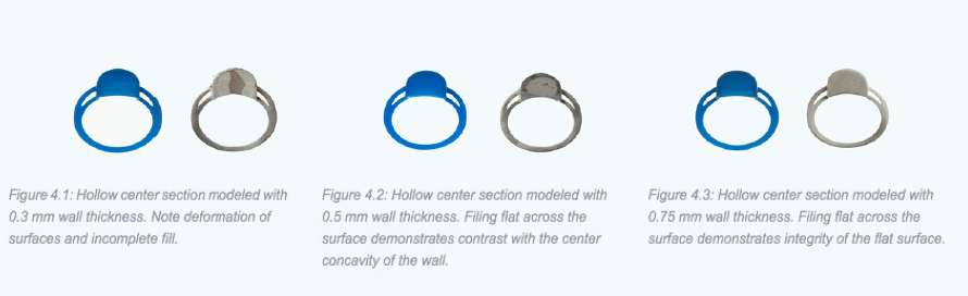
At 0. 5 mm wall thickness (Fig 4.2), we see reliably complete fill, but there is some distortion and concavity in the side walls. A file was used to make several cuts along the surface photographed to show that the surface is indeed concave. It would be possible to continue filing to make that surface perfectly flat, but this would result in
dangerously thin walls that would not withstand the stress of a customer wearing the ring.
A wall thickness of 0 .75 mm (Fig 4 .3) works well at this scale, with reduced distortion. The same several cuts of a file across the surface yield very minor surface depressions that can easily be filed to flat without much loss in wall thickness The result is a structurally strong ring that will hold up to everyday wear.
Larger pieces must be designed at a practical weight for printing and manufacturing.
If a piece is too heavy, it will require a stronger network of supports during printing so that it does not detach from its build supports during the peel process.
From a practical standpoint, heavy pieces increase material costs, both final cast metal and resin used for printing, and perhaps cause end-customer dissatisfaction by being uncomfortably heavy to wear. If a piece is designed too light, it faces potential distortion caused by the peel and cure forces.
An overly light piece may not be castable due to walls or components too thin to fill properly during the casting process, as noted above for small scale pieces.
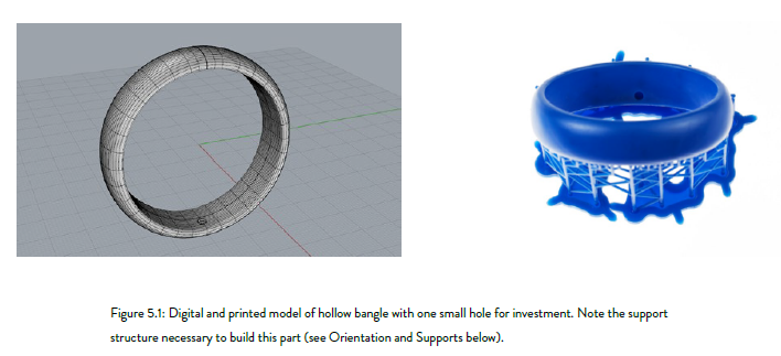
As is common practice in the hand fabrication of jewelry, large pieces should be designed as hollow forms, with a minimum wall thickness that will maintain structural integrity and allow for everyday wear. The bangle bracelet pictured, with a width of 18 mm, has a wall thickness of 0.9 mm.
Three versions are shown over the next two pages (Fig: 5. 1 – 5.3) The first (Fig 5 .1) is printed with a continuous surface all around, with the exception of a small 3 .5 mm hole to allow for internal cleaning with isopropyl alcohol (IPA) and filling of the hollow bangle with investment for casting.
Figure 5.1: Digital and printed model of hollow bangle with one small hole for investment. Note the support structure necessary to build this part (see Orientation and Supports below).
The surface produced by the 3D printer is smooth and consistent, giving a form and surface ready for welding a plate in the small hole and final finishing. Unfortunately, this piece cannot be cast.
Figure 5.2: Digital model of hollow bracelet with multiple large openings in the inner surface to allow for successful investment and casting.

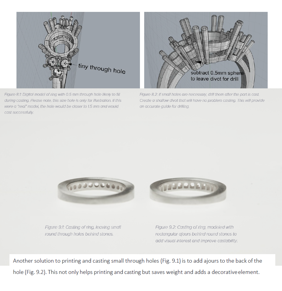
The second version (Fig 5.2) simply adds more and larger access holes to the hollow inner of the bangle. These holes can be decorative and serve as an integral part of the design. The third version (Fig 5.3) builds the bangle in multiple parts.
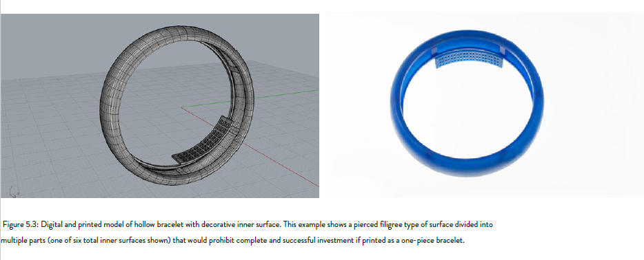
Use this approach if you want to close off all surfaces, or if you want to create a decorative pierced pattern inside the bracelet that has piercings too fine to successfully invest and cast the bangle in one piece.
Building supports and keys in the model greatly simplifies the assembly.
Figure 5.3: Digital and printed model of hollow bracelet with decorative inner surface. This example shows a pierced filigree type of surface divided into multiple parts (one of six total inner surfaces shown) that would prohibit complete and successful investment if printed as a one-piece bracelet.
NOTES ON CASTING AND INVESTMENT:
The technique of lost wax casting (or in our case, lost resin casting) relies on encasing the part with a refractory material, investment, that forms a mold of the part and allows molten metal to fill the precise area of the part after that part is completely removed by burning at high temperature. Investment is extremely hard, but as with most extremely hard materials, it is also very brittle. Digital design for casting in metal requires understanding and planning for the negative (investment) as well as positive (resin, or metal after casting) spaces.
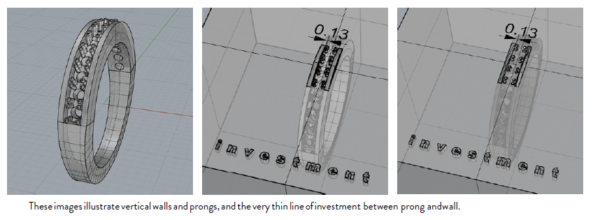
In the example above, consider what the very small space between prong and wall means to the investment. Once the resin part is burnt out, this very small length of investment must withstand the force of molten metal rushing into the mold at high velocity. In this case, it will not .
This yields two extremely important results:
1). The investment breaks and the metal simply runs freely between prong and wall.
2). There are now tiny particles of investment floating in the mix of molten metal. These particles cause a void, and they also may appear in the metal close to the surface. There are few things worse than the final polish revealing bits of investment.
These images illustrate vertical walls and prongs, and the very thin line of investment between prong and wall.
One way to solve this issue is by adding draft to side walls and prongs (Fig 7. 4 - 7 .6).
“Draft” is angling those walls and prongs so that they taper from a thicker base to a thinner top, and typically a 5-degree draft angle is sufficient to improve castability without being obtrusive. If the design supports it, a larger draft angle will always help.
This creates a stronger part with visually thinner edges and yields a larger space between the upper part of the wall and the prong for the investment to be more rigorous in withstanding the casting forces. There may still be some closing of the space where the prong meets the wall at its base from printing and casting artifacts, but the upper part of the space will be defined and easier to cast.
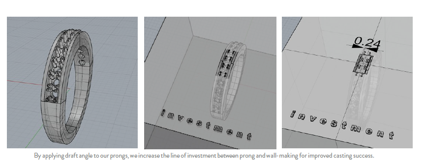
This space, which previously only existed in the digital file because it was too small to be cast before draft was added, allows for more secure casting, and provides a guide for setting the stones. Although beyond the scope of this paper, draft in such details in a model also improves results in the mold making and subsequent wax injection processes.
By applying draft angle to our prongs, we increase the line of investment between prong and wall-making for improved casting success.
HOLES
For all practical purposes, through holes should have a minimum diameter of 0. 5 mm, and that diameter only should be used for holes in very thin material. It is possible to cast smaller holes, but results may not be consistent in both printing and casting.
In the ring pictured below (Fig .8. 1), a 0.5mm hole was modeled in the center of the under bezel of settings (most likely there is no need for a hole this small, but it is a good example!). Such a small hole in a relatively thick piece of metal risks the investment breaking during casting and the hole filling. A filled hole can always be drilled through, but as mentioned above, seeing a filled hole means that there are particles of broken investment floating around in the casting looking to cause mischief.
One solution is to simply indicate the ends of the through hole by differencing a sphere at both ends of the hole, providing a guide for drilling (Fig 8.2)
INTERNAL CORNERS
As we saw earlier, it is important to consider the negative spaces in your design, especially internal corners that may cause a problem with sharp edges of investment breaking off into the piece during casting. Consider the flow of metal into the investment mold, and how to make that flow as smooth as possible. Sharp edges, rough finishes, and even the sharp or depressed edges from supports that weren’t removed smoothly can cause turbulence in the liquid metal. In the best case, the casting will be fine. In the worst case, this turbulence can cause porosity (think of waves splashing).
Whenever possible, fillet internal edges (Fig 10 .1 – 10.2), and if the design can support it, external edges as well (Fig 10 . 3 - 10 . 4) Spend time finishing your print, smoothing surfaces, and removing any artifacts.
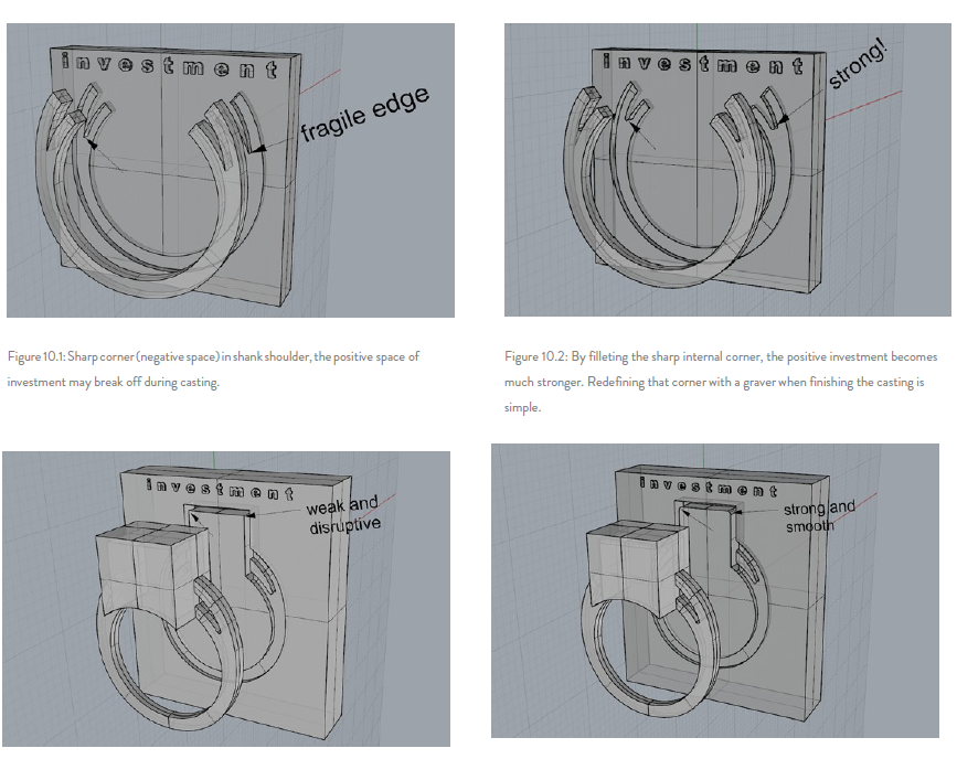
Figure 10.1: Sharp corner (negative space) in shank shoulder, the positive space of investment may break off during casting.
Figure 10.2: By filleting the sharp internal corner, the positive investment becomes much stronger. Redefining that corner with a graver when finishing the casting is simple.
ENGRAVED DETAILS
(we do not recommend engraving in 3D models and is currently out-of-scope for Gildform Production)
Everyone wants to engrave inside rings! If the images and text are large enough, engraving should not cause any issues. HOWEVER, We do no recommend engraving in the 3D Model as it may cause many quality issues in casting and finishing, resulting in a poor quality. If very fine engraving is desired, the best solution is for us to laser engrave or stamp the pieces.
In the examples shown (Fig 11. 1 – 11. 4), the letter E was used in various fonts, from block to script. One ring has the letters engraved to a depth of 0 . 3 mm (Fig 11 1), the other a depth of 0. 5 mm (Fig 11 3).
As with any features built into the piece as opposed to on top of it, such negative spaces should be created with draft. The height of the smallest letters is 1. 5 mm, and the smallest letters of the ornate script tend to fail in both depths. This is mostly due to the investment not surviving those thin and intricate details, and also due to approaching the limit of your printer to print very small negative features. These smallest letters seem to do slightly better in the shallower 0. 3 mm depth, due to the investment filling these spaces being shorter and thus stronger. When the investment does not survive, particles of that failure can cause damage to the casting. For very small engravings, do it after the casting; for larger letters or images, be aware of how those features will print and invest.
We do not recommend engraving in 3D models and is currently out-of-scope for Gildform Production
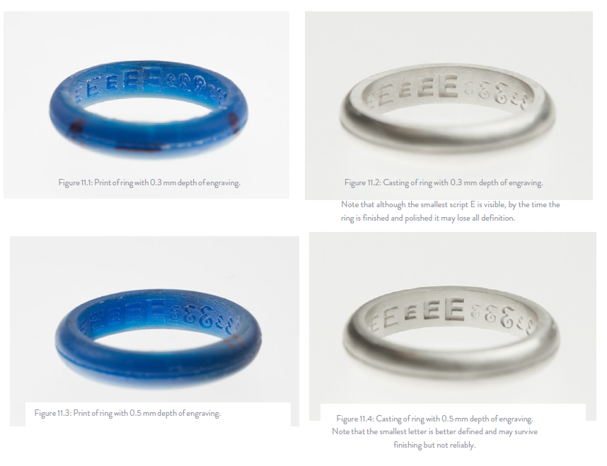
Figure 11.1: Print of ring with 0.3 mm depth of engraving. Figure 11.2: Casting of ring with 0.3 mm depth of engraving.
Note that although the smallest script E is visible, by the time the ring is finished and polished it may lose all definition.
Figure 11.3: Print of ring with 0.5 mm depth of engraving.
Figure 11.4: Casting of ring with 0.5 mm depth of engraving. Note that the smallest letter is better defined and may survive finishing but not reliably.
SURFACE RELIEF
When adding fine details raised above the surface, consider the finishing process. Even the most perfect casting comes out with a matte surface, and in the case of resin prints, there will be some artifacts due to the creation of layers in the printing process.
Although our 3D Printers yield an exceptionally smooth surface, those microscopic layers may still remain visible in the casting. The surface of a casting is typically tumbled or pin finished (a burnishing process), then polished (a subtractive process), to yield the final finish.
The polishing process removes material, and if the surface detail is too fine, that detail will be diminished and lose its visual effect during the polishing process. The simple and effective solution is to exaggerate the relief.
The image below (Fig 12) shows a 0 . 3 mm diameter “wire” in a grooved ring shank. This will be lost or diminished in effect by the time the piece is finished. By exaggerating the depth of the groove and the height of the “wire” while maintaining the same 0 3 mm width, the final finished pieces will better achieve the desired effect.
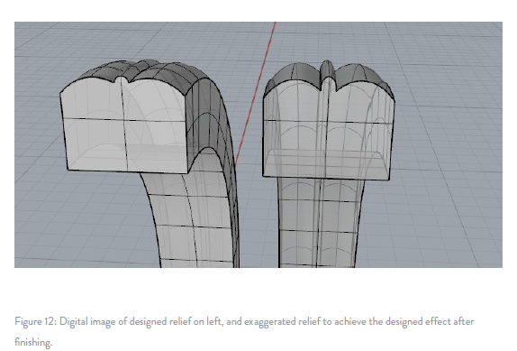
Figure 12: Digital image of designed relief on left, and exaggerated relief to achieve the designed effect after finishing.
WATERTIGHT MODELS
In order to end up with the best print possible, it is important to make sure your digital model is “watertight,” meaning that all surfaces of the solid object are joined without any open seams. Check for open seams using analyze commands such as “show edges” found in your CAD program. Repairing models is not always easy and is beyond the scope of this paper.
Another important detail to note is the difference between grouped components and booleaned components. Grouping collects a number of individual constructions and allows them to be manipulated as a single part, while the boolean process creates one unified construction from a number of individual constructions.
Our Printer Software will not be able to correct all of the errors in your file and allows it to print anyway Pictured (Fig 1.3) is the same part, one from a grouped file with some open edges, and the other from a booleaned and watertight file.
The most reliable approach is to check and repair your digital models before uploading them on Gildform Marketplace and delivering them to the customers.
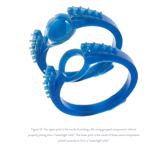
Figure 13: The upper print is the result of printing a file using grouped components without properly joining into a “watertight solid.” The lower print is the result of those same components joined correctly to form a “watertight solid.”
CONCLUSION
The information discussed in this white paper should be used as a guideline for building successful digital models, but there is never only one correct way to model a design.
We are here to help at every step of the way! For questions, please email hello@gildform.com
Text - Originally published by Form Labs